3.2.4 Sixty Second Timer
This is my Sixty Second Timer, it is made with both SSI and MSI logic.
|
In this project we had to create a 60 second timer in Multisim that has a stop and a reset button, also when it reaches 60 it has to stop counting.
Design Specifications: • The two output displays are common cathode seven-segment displays. • Current limiting resistors (150 Ω - 270 Ω) must be used. • Each display will use a 74LS48 BCD-To-Seven-Segment display driver. • The ones-unit display (0-9) is controlled by an asynchronous counter designed with a 74LS93 MSI counter IC. • The tens-unit display (0-6) is controlled by an asynchronous counter designed with SSI logic gates (D or J/K). • Any additional logic may be used as needed to support the counter How this circuit works is if you keep the switch on ground the entire circuit stops counting and goes to 00 from wherever the count is currently at, and if the switch is on VCC then the circuit counts from 0 to 60 then stops until you flip the switch again. How this circuit works on the logic level is it uses three D flip-flops on the top and some other assorted logic gates to count from 1 to 6 on the left side, and then on the bottom it uses a medium scale integrated circuit that does essentially the same thing as four flip-flops only it is a little bit more limited, such as the fact that it cannot count down, only up, and it cant be set to start at a specific number, it must start at 0. The regular D flip-flops on the top are not as limited but are much more difficult to configure. The way this counter works is it takes one clock pulse from the clock which is 1Hz and sends it through the first flip flop, this output goes into both the D port on the flip flop and the clock input of the next flip flop, this means that when a pulse from the clock enters the flip flop then the output will change. Since the output goes into the next input this effectively divides the clock speed in half so now the clock pulse going into this flip flop is 0.5Hz same with the next one. Using leaders off of each of the outputs we can enter this information into a binary driver that converts binary to seven segment display signals and then from there directly into a seven segment display. Before these signals hit the driver they have one more task to complete, in order to stop the count where we want it to we have to take leaders from the four binary inputs, if we do this correctly using Inverters and regular wires we are able to take the binary number and use that as one signal to send to the reset button which will effectively stop the count anytime it reaches that certain number. Conclusion: This project overall taught me a lot about how to use D Flip-Flops to make a counter count to anything I want and either start over, stop, or reset. This project only utilized D Flip-Flops, not JK Flip-Flops which are the more common ones but nonetheless it was a valuable learning experience. If I had to do this project over again I would probably spend a little less time making sure the circuity looked nice and instead just finished the project, because I turned mine in late. |
The completed 60 timer design in multisim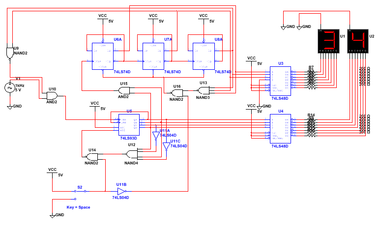
|
