3.3.1 MSI Asynchronous Counter
|
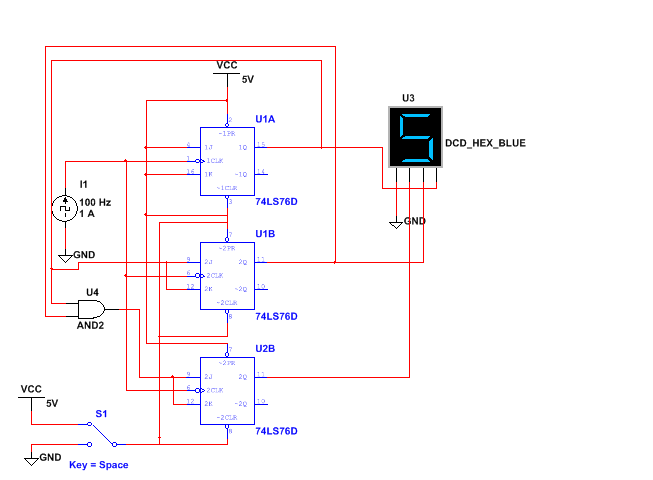
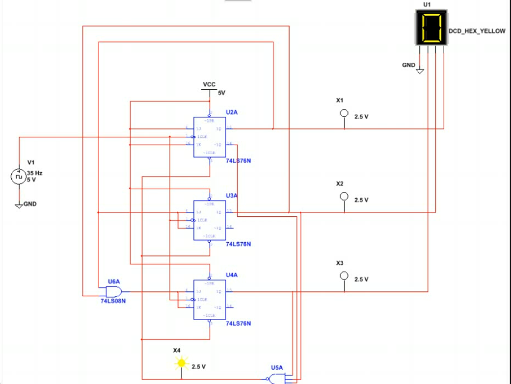
For this project we had to build a synchronous mod 6 up counter in Multisim. We had to observe it and then we had to modify it to be a down counter. After we finished with the first circuit we had to make a new circuit that was essentially the same thing except we could modify when the circuit stopped, and reset.
Essentially how this circuit works is it starts out at the clock, from the clock it goes to the clock input of the first JK Flip Flop, then the output goes to the input of the next JK Flip Flop which halves the signal effectively creating binary code. the signal then goes to the next JK Flip Flop which halves it again then all of the signals go to the hex display which turns the binary code into numbers. The single difference between the first circuit and the second is the before the signal gets the the hex display there a few leader wires that go off into an and gate, this determines what number the circuit will stop at. If you wanted to stop at the number 5 then you would put leader wires from the two first wires going to the hex display (the ones on the far right) and on the other two would have inverters coming from them, then when the circuit counted to 5, it would send a signal through the wires leading to a four input AND gate. From the AND gate it goes to the CLR and resets the circuit which effectively resets the count at 5. |
|
